

 EN

 English
 русский
 Español
Standard Air Operated Pinch Valves
Cat:Air Operated Pinch Valves
Air Operated pinch valves offer a unique and cost-effective solution for fluid control problems. The secret lies in the rubber valve sleeve - the onl...
See DetailsA yogurt line restarts after a weekend filter-housing change, runs its full CIP cycle, and still fails the post-clean swab check. The element was the right micron rating. The housing was the right alloy. The problem was a 140 mm capped blowdown branch on the strainer upstream: it never fills with cleaning solution, never drains, and quietly holds product residue between shifts. Nothing on the purchase order would have caught it. The installation drawing would have.
That pattern repeats across dairy, brewing, and bioprocessing projects. Filtration hardware is specified carefully and installed casually, and the installation is usually where hygienic compliance is actually won or lost.
The short answer: in sanitary service, a filter or strainer is judged on three installation requirements before mesh size or pressure drop matter. It must drain completely by gravity when the line is emptied, it must contain no dead leg longer than roughly two branch diameters, and it must open for element removal without tools, spills, or exposed product. Get those three right and most audit findings disappear. Get them wrong and even a perfectly rated element will fail inspection.
Content
In ordinary industrial piping a Y-strainer is a debris catcher. In a sanitary system it is also a product-contact vessel: it holds liquid, it is cleaned in place rather than dismantled daily, and its interior may be inspected during a hygiene audit. Once you accept that framing, three properties become non-negotiable, and everything else follows from them.
Most installation defects are geometric, and most geometry problems come from copying general-piping habits into a hygienic line. The rules are short but unforgiving.
The valves on either side of the strainer deserve the same scrutiny. A ball valve leaves a cavity behind the seat that no CIP return will scour, and a butterfly disc creates a shadow in the pipe. Full-bore elastomer-seated valves are often the cleaner choice on particulate or abrasive duties, because there is no seat pocket to trap solids and nothing to obstruct a pig or a flush.
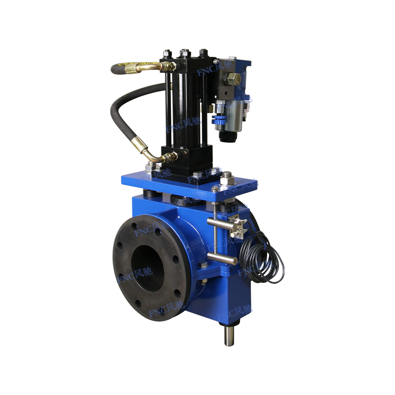 Closed Body Pinch Valve for Abrasive Slurry ServiceFull-bore enclosed pinch valve with a self-cleaning rubber sleeve, designed for abrasive and slurry duties where seat pockets and flow obstruction are concerns.View Product →
Alloy selection is usually right on the datasheet and wrong at the weld. For product contact, 316L bodies and 316L mesh are the working baseline; 304 is a false economy in chloride CIP regimes, and brass or zinc-plated components have no place in the wetted path.
The table below condenses how the same three principles translate into different hardware decisions across common sanitary duties.
Across commissioning and re-audit reports on hygienic filtration installations, the same small set of defects keeps appearing. Notice how little of it is about the element itself.
Two-thirds of findings sit in geometry that a 15-minute drawing review would catch. That is why we now mark up the drain path on the isometric before the housing is released for fabrication, rather than checking it after installation when every correction means cutting a ferrule out of a welded line.
The split matters practically. Dairy and brewing installations usually tolerate a manually cleaned basket because the line opens daily, while pharma leans toward in-line housings that stay closed through SIP. Particulate food duties sit awkwardly in between: they carry solids that load a screen quickly, so the pump upstream or downstream has to tolerate the same solids. On those lines, a peristaltic or hose pump paired with a coarse strainer is a more honest combination than a fine screen and a centrifugal pump that cavitates every time the basket blinds.
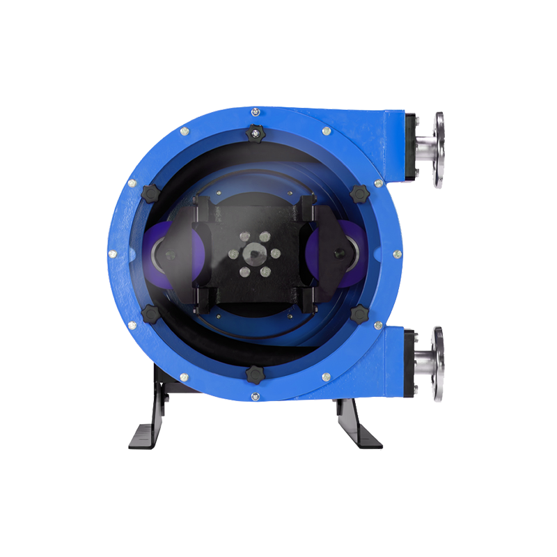 Rollers Hose Pump for Abrasive and Solids-Laden MediaPeristaltic hose pump with only the rubber hose contacting the medium, suited to abrasive slurries and solids-laden duties where valves and seals would wear.View Product →
This sequence keeps filtration work out of the rework column, and it is short enough to run on every project regardless of size.
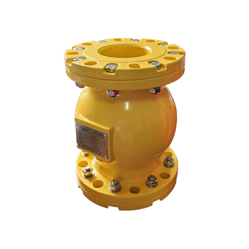 Standard Air Operated Pinch Valves for Abrasive MediaPneumatic pinch valves use a rubber sleeve as the only wetted flow path, offering zero-leakage closure and low resistance in abrasive or corrosive duties.View Product →
An installation is only hygienic if it stays that way after the first element change. Three habits carry most of the load: trend differential pressure instead of waiting for a complaint, inspect the screen at every CIP cycle for deformation and wire damage, and keep a spare element and gasket set on site so a torn mesh never gets straightened and refitted.
One last point that catches experienced buyers: the isolation valves around the strainer are part of the hygienic envelope, not accessories. Their pressure rating, bore, and drain behaviour decide whether the strainer can actually be cleaned and emptied. It is worth checking pinch valve pressure ratings and operating limits against your CIP and SIP envelope before the line is frozen, because a valve that cannot take the steam cycle will undo a well-designed filter installation in a single shift.
Get the drain path, the dead legs, and the access envelope right at drawing stage, and the rest of the specification — mesh, alloy, finish — will do its job quietly for years.
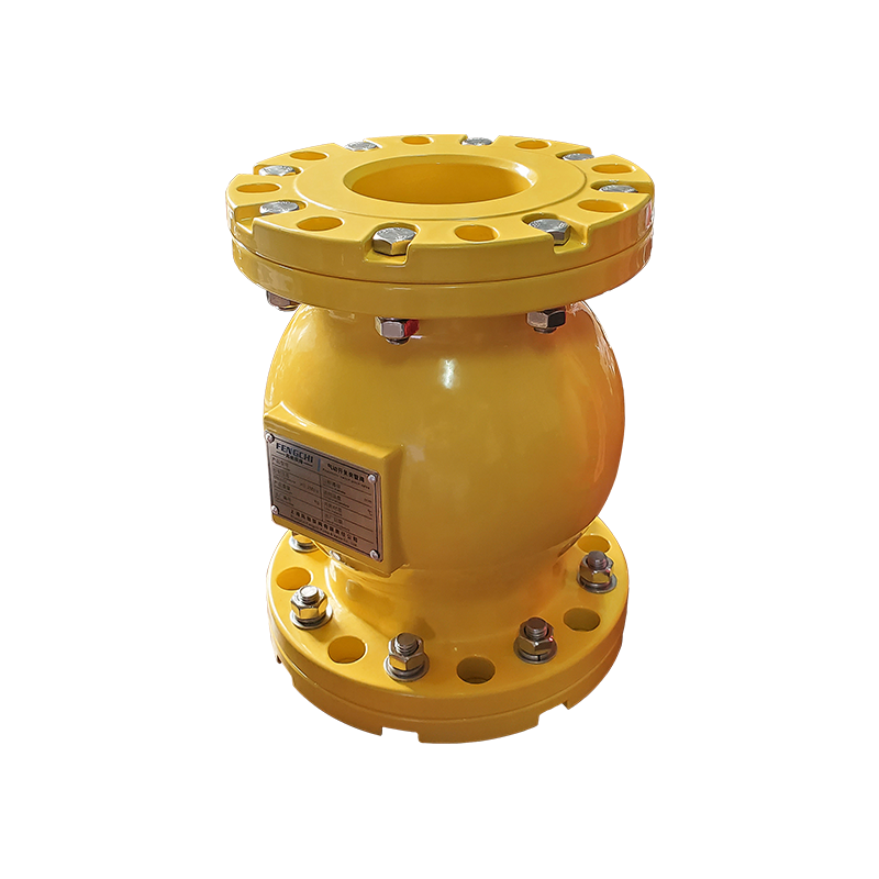
Air Operated pinch valves offer a unique and cost-effective solution for fluid control problems. The secret lies in the rubber valve sleeve - the onl...
See Details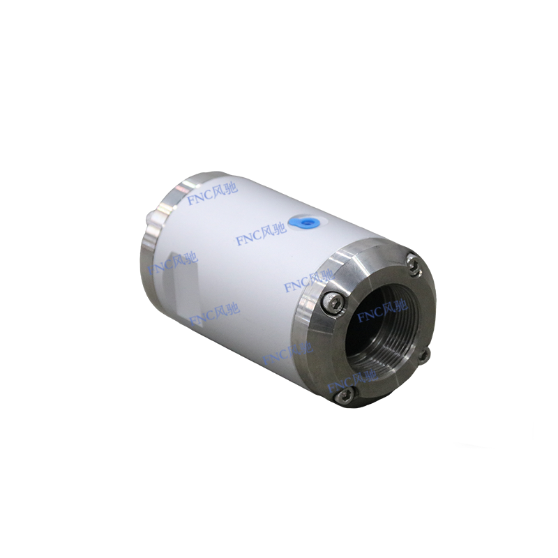
Air Operated pinch valves offer a unique and cost-effective solution for fluid control problems. The secret lies in the rubber valve sleeve - the onl...
See Details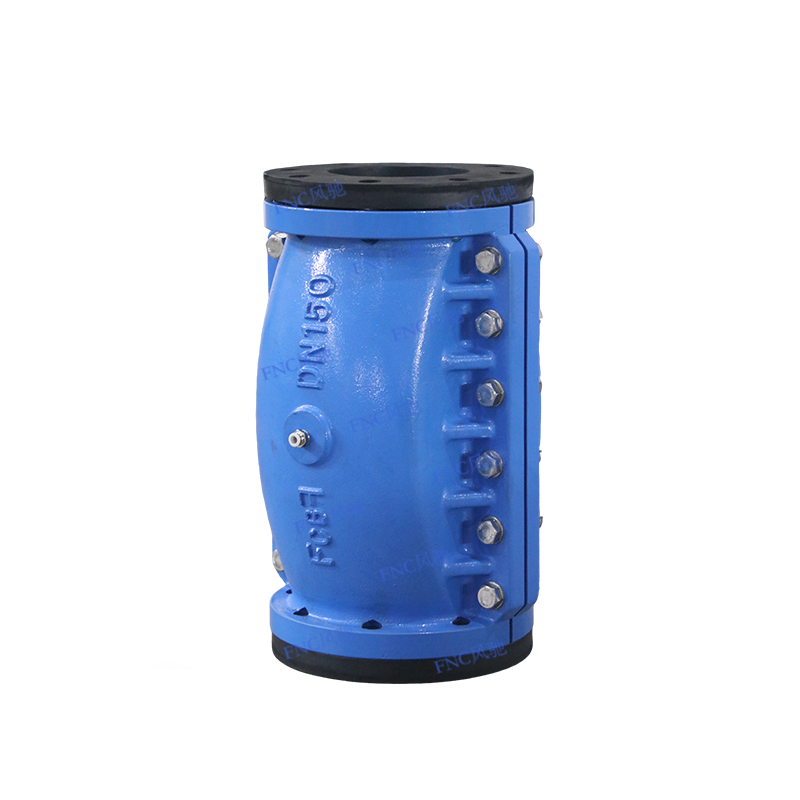
Air Operated pinch valves offer a unique and cost-effective solution for fluid control problems. The secret lies in the rubber valve sleeve - the onl...
See Details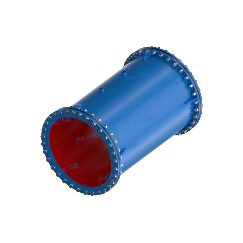
Air Operated pinch valves offer a unique and cost-effective solution for fluid control problems. The secret lies in the rubber valve sleeve - the onl...
See Details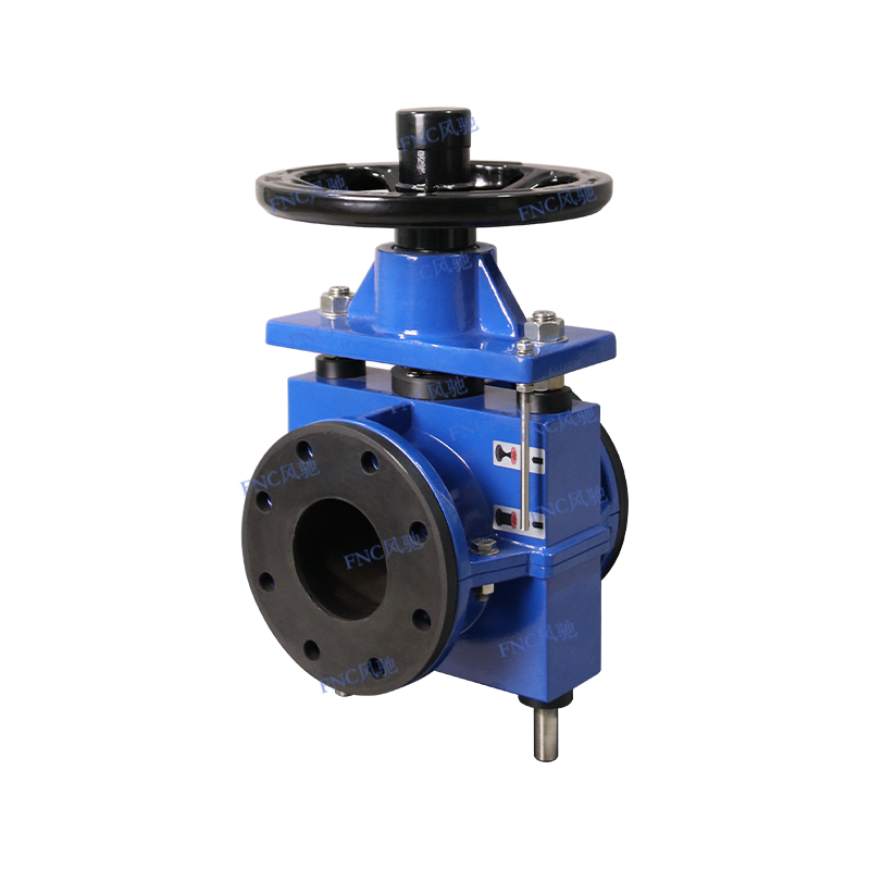
The operating principle of the FNC® enclosed pinch valve is straightforward. When in the open position, the valve provides a full-bore passage, allowi...
See Details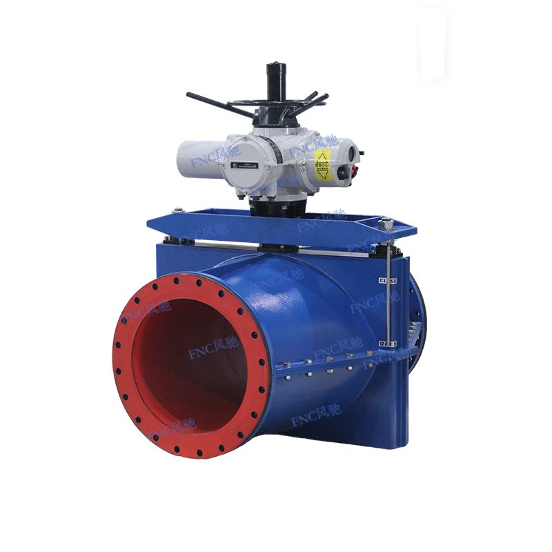
Compared to ordinary pinch valves, large-diameter pinch valves have much higher production requirements. As the “core component” of the pinch valve, t...
See Details
Phone: +86-136 7173 4086

Tel: +86-563 5033 866

Email: red@pinchvalves.com.cn

Address:
