
 EN
EN

 English
 русский
 Español
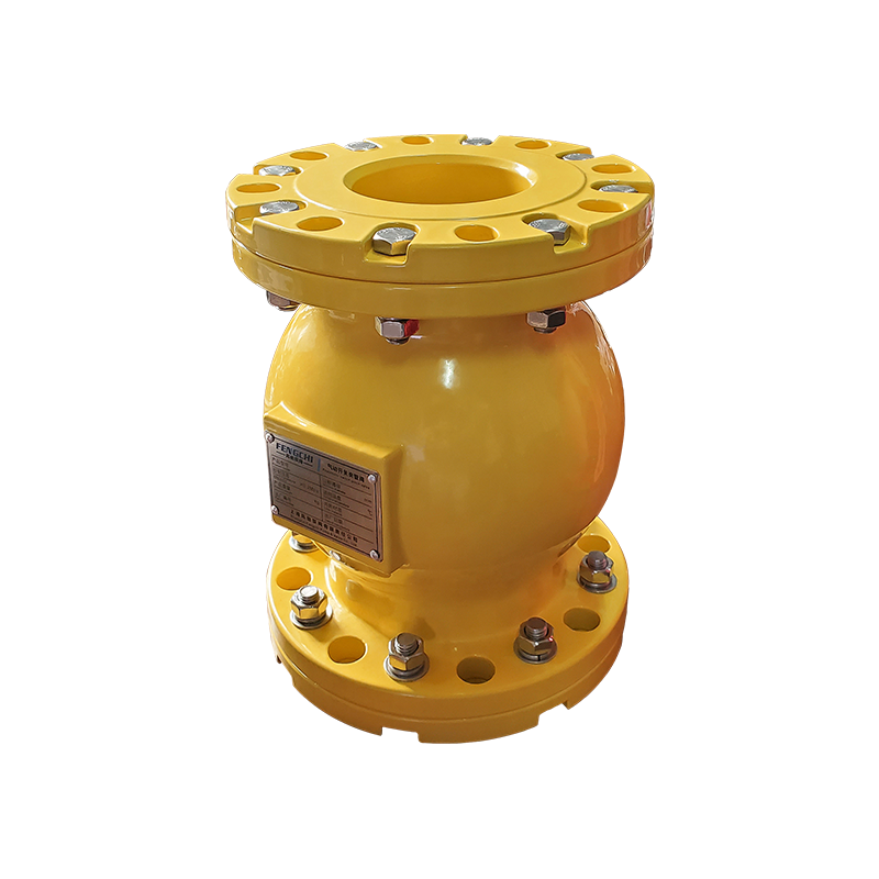
Mini Air Operated Pinch Valves
Cat:Air Operated Pinch Valves
Air Operated pinch valves offer a unique and cost-effective solution for fluid control problems. The secret lies in the rubber valve sleeve - the onl...
See DetailsContent
Response time represents one of the most critical performance parameters for air operated pinch valves, particularly in applications requiring rapid process adjustments or emergency shutoff capabilities. The actuation speed encompasses both opening and closing cycles, measured from the moment the control signal initiates until the valve reaches its final position. Air operated pinch valves typically achieve full stroke times ranging from one to five seconds, depending on valve size, air supply pressure, actuator design, and the complexity of pneumatic control circuitry. Applications involving batch processes, quick-dump requirements, or safety interlocks demand faster response times, while gradual flow modulation applications may tolerate slower actuation speeds.
Several factors influence response time performance. Air supply pressure directly affects actuation force and speed, with higher pressures generally producing faster valve movement. However, excessively high pressures can cause sleeve damage through rapid compression cycles, creating a balance between speed requirements and component longevity. The distance between the air supply and the valve, along with tubing diameter and fittings, introduces pneumatic lag that delays response. Buyers should specify maximum acceptable response times based on process control requirements and verify that manufacturers can provide documented performance data under conditions matching the intended application, including pressure variations and temperature extremes.
Air consumption directly impacts operational costs, particularly in facilities where compressed air represents a significant energy expense. Air operated pinch valves consume air in two distinct modes: dynamic consumption during actuation cycles and static consumption for maintaining valve position. Single-acting actuators with spring return mechanisms consume air only during the powered stroke, using spring force for the return movement. This design minimizes static air consumption but requires sufficient spring force to overcome process pressure and sleeve resistance. Double-acting actuators use air pressure for both opening and closing strokes, providing greater force control but potentially increasing overall air consumption.
Calculating total air consumption requires understanding cycling frequency, valve size, actuator volume, and supply pressure. A typical four-inch air operated pinch valve might consume between 0.5 to 2.0 cubic feet of air per cycle, depending on actuator design and operating pressure. In applications with frequent cycling, annual air consumption can become substantial. Energy-efficient designs incorporate features such as low-volume actuators, air saving positioners, and exhaust flow restrictors that reduce air usage without compromising performance. Buyers operating in energy-conscious environments should request detailed air consumption specifications and consider the following efficiency factors:
Cycling capacity defines the number of complete open-close cycles a valve can perform before requiring maintenance or component replacement. Air operated pinch valves demonstrate exceptional cycling capacity compared to traditional valve designs, primarily because the flexible sleeve tolerates repeated compression without developing the wear patterns that plague metal-seated valves. Quality pinch valve sleeves routinely achieve 500,000 to over one million cycles in non-abrasive service, though abrasive media significantly reduces this expectation. The cycling capacity becomes particularly important in automated processes, batching operations, and applications with frequent start-stop sequences.
Sleeve material selection profoundly influences cycling durability. Natural rubber sleeves excel in abrasion resistance but may exhibit reduced flex fatigue life compared to synthetic compounds specifically formulated for high-cycle applications. Reinforcement layers within the sleeve construction, typically fabric or wire, distribute stress during compression cycles and prevent localized failure points. The actuator mechanism also affects overall cycling capacity, as pneumatic components including seals, bearings, and linkages experience wear with repeated operation. Premium actuator designs incorporate long-life seals, hardened bearing surfaces, and robust linkage mechanisms that match or exceed sleeve cycling capabilities.
| Service Conditions | Expected Cycle Life | Limiting Factors | Maintenance Interval |
| Clean water, ambient temperature | 1,000,000+ cycles | Flex fatigue | Annual inspection |
| Mild abrasives, moderate solids | 500,000-750,000 cycles | Abrasive wear | Semi-annual inspection |
| Heavy slurries, sharp particles | 200,000-400,000 cycles | Erosion, cutting | Quarterly inspection |
| Corrosive chemicals, elevated temp | 300,000-600,000 cycles | Chemical degradation | Quarterly inspection |
Sealing performance determines whether an air operated pinch valve can achieve bubble-tight shutoff or merely provide throttling control with acceptable leakage. The pinch valve's sealing mechanism differs fundamentally from traditional valves, relying on complete sleeve collapse rather than metal-to-metal or elastomer-to-metal contact. When properly sized and actuated with sufficient force, pinch valves achieve zero leakage in both directions, meeting or exceeding ANSI Class VI shutoff requirements. This bidirectional sealing capability proves particularly valuable in applications involving backpressure, reverse flow conditions, or processes requiring isolation for maintenance.
Several factors affect sealing reliability over the valve's service life. Sleeve material must retain sufficient elasticity to collapse completely under actuator force while recovering its shape when released. Chemical attack, thermal aging, and physical abrasion gradually reduce elasticity, eventually compromising seal integrity. Process pressure opposes sleeve closure, requiring greater actuator force to achieve shutoff as pressure increases. Buyers should verify that the selected actuator provides adequate closure force across the full range of expected process pressures, including transient conditions. Particulate matter can embed in the sleeve surface or lodge in the closure area, creating leak paths that worsen with repeated cycling.
The fail-safe position defines where the valve moves upon loss of air supply, representing a critical safety consideration in process design. Spring-return actuators naturally assume either fail-open or fail-closed positions based on spring configuration. Fail-closed designs use air pressure to open the valve, with spring force closing it when air is lost, providing automatic process isolation during power or air supply failures. Fail-open configurations reverse this arrangement, ensuring continued flow during utility interruptions. The choice between fail-safe positions depends entirely on process safety analysis, with considerations including product containment requirements, emergency venting needs, and consequences of unexpected flow interruption.
Control precision indicates how accurately an air operated pinch valve can maintain a specific flow position or respond to incremental control signals. While pinch valves excel at on-off service, achieving precise throttling control requires additional instrumentation and actuator sophistication. Basic pneumatic actuators with simple solenoid valves provide two-position control suitable for isolation or diversion applications. Adding a pneumatic positioner enables proportional control, where the valve position corresponds to an input signal from a process controller, typically a 4-20 mA current or 3-15 psi pneumatic signal.
The inherent relationship between sleeve compression and flow rate affects control linearity. Unlike globe valves with characterized trim, pinch valves exhibit a relatively linear flow characteristic through mid-range positions but demonstrate reduced sensitivity near fully open and fully closed positions. Digital positioners with microprocessor control can compensate for these non-linearities through characterization algorithms, improving control precision. Hysteresis, the difference in valve position between increasing and decreasing control signals, results from friction in the actuator mechanism and sleeve deformation characteristics. High-quality positioners minimize hysteresis to less than one percent of full stroke, enabling tight process control.
Advanced air operated pinch valves increasingly incorporate diagnostic capabilities that monitor performance parameters and predict maintenance requirements before failures occur. Smart positioners track metrics including stroke time, air consumption, supply pressure variations, and deviation between commanded and actual positions. Analyzing these parameters over time reveals degradation patterns indicating sleeve wear, actuator seal leakage, or supply system problems. Diagnostic systems can trigger alarms when performance metrics exceed acceptable thresholds, enabling scheduled maintenance rather than reactive repairs following unexpected failures.
Partial stroke testing represents another valuable diagnostic feature, particularly for valves in safety-critical applications that remain stationary for extended periods. The system periodically commands a small valve movement without fully interrupting process flow, verifying mechanical freedom and actuator functionality. This testing identifies problems such as sleeve adhesion, actuator binding, or air supply restrictions before the valve is needed for emergency service. Integration with plant distributed control systems allows centralized monitoring of multiple valves, trend analysis, and automated maintenance scheduling based on actual operating conditions rather than arbitrary time intervals.
Environmental conditions at the installation site significantly affect air operated pinch valve performance and longevity. Ambient temperature extremes influence both the pneumatic control system and the valve sleeve. Cold environments can cause moisture in the air supply to freeze within control valves and actuators, potentially blocking air passages or damaging components. Installing air dryers, heat tracing, or insulated enclosures mitigates these risks. Conversely, high ambient temperatures accelerate elastomer aging in the sleeve and pneumatic seals, reducing service life even when process media remains within acceptable temperature limits.
Corrosive atmospheres, particularly those containing chlorine, ozone, or industrial pollutants, attack exposed elastomer components and metal actuator housings. Specifying corrosion-resistant actuator materials such as stainless steel or aluminum with protective coatings extends equipment life in harsh environments. Dust, moisture, and contaminants entering pneumatic control components cause erratic operation and accelerated wear. Installing filters, regulators, and lubricators in the air supply line ensures clean, dry air at consistent pressure. Physical installation factors including valve orientation, accessibility for maintenance, and piping stress also influence performance. Buyers should provide detailed site information enabling manufacturers to recommend appropriate accessories and configuration options that ensure reliable operation throughout the valve's intended service life under actual installation conditions.

Air Operated pinch valves offer a unique and cost-effective solution for fluid control problems. The secret lies in the rubber valve sleeve - the onl...
See Details
Air Operated pinch valves offer a unique and cost-effective solution for fluid control problems. The secret lies in the rubber valve sleeve - the onl...
See Details
Air Operated pinch valves offer a unique and cost-effective solution for fluid control problems. The secret lies in the rubber valve sleeve - the onl...
See Details
Air Operated pinch valves offer a unique and cost-effective solution for fluid control problems. The secret lies in the rubber valve sleeve - the onl...
See Details
Compared to ordinary pinch valves, large-diameter pinch valves have much higher production requirements. As the “core component” of the pinch valve, t...
See Details
The operating principle of the FNC® enclosed pinch valve is straightforward. When in the open position, the valve provides a full-bore passage, allowi...
See Details
Phone: +86-136 7173 4086

Tel: +86-563 5033 866

Email: red@pinchvalves.com.cn
Address: