

 EN
EN

 English
 русский
 Español
Closed Body Pinch Valve
Cat:Pinch Valves
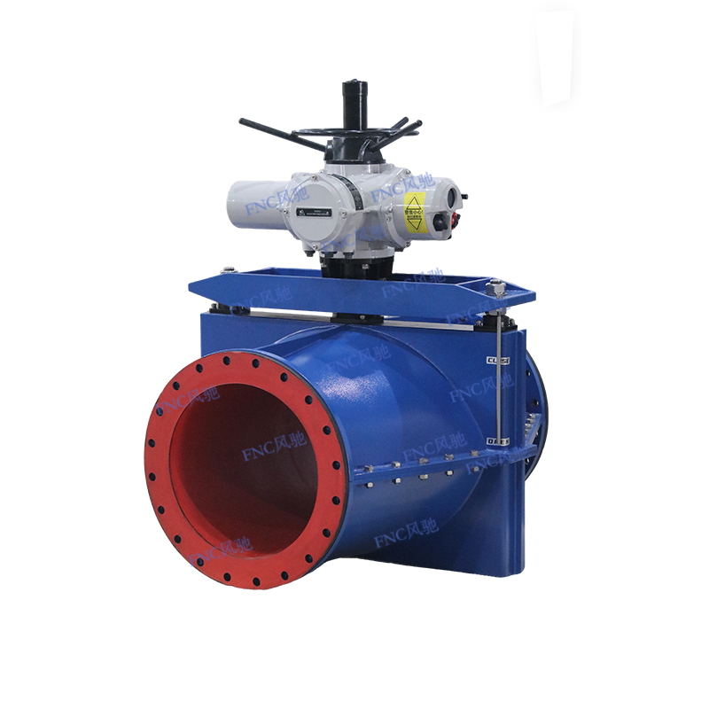
The operating principle of the FNC® enclosed pinch valve is straightforward. When in the open position, the valve provides a full-bore passage, allowi...
See DetailsThe choice between a pinch valve and a knife gate valve turns on a single practical question: whether the application prioritizes a bubble-tight, zero-leakage shutoff on abrasive slurries, or a cost-effective, compact isolation point for sludge and solids that can tolerate minor leakage. For slurries with coarse, sharp particles exceeding 1/8 inch diameter, a pinch valve with a full-port elastomer sleeve provides roughly three to five times the service life of a knife gate valve with metal seats. The knife gate valve, however, remains the standard where space is tight, initial capital cost must be minimized, and the process fluid carries fibrous solids that would tear a flexible sleeve.
Content
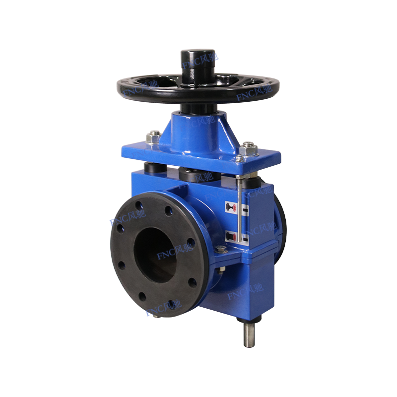
A pinch valve isolates flow by mechanically compressing a resilient elastomer sleeve until the two internal walls meet and form a tight seal. The closure mechanism can be a simple single-side pinch bar, a dual-pinching mechanism that squeezes from both sides, or a pneumatically actuated concentric closure that collapses the sleeve uniformly. The sleeve itself is the only component contacting the process fluid, eliminating the need for body cavity purging or seat flushing. The sleeve's full-port profile matches the pipe's inner diameter exactly when open, yielding a pressure drop coefficient (Cv) identical to straight pipe.
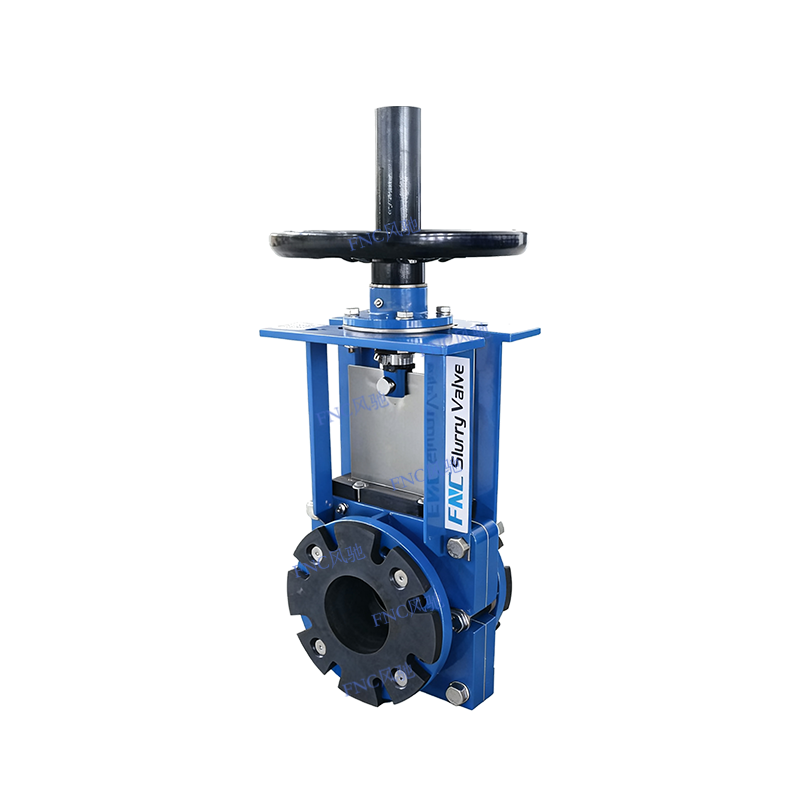
A knife gate valve drives a beveled steel blade, often stainless steel with a hardfaced leading edge, through a resilient seat or directly across a metal-to-metal interface into a stuffing box at the bottom of the body. The blade shears through suspended solids and fiber bundles during the closing stroke. Unlike a wedge gate that relies on mechanical wedging for sealing, the knife gate depends on the differential pressure across the disc to push it against the downstream seat face, making it a unidirectional sealing valve by design.
The slurry's solid particle size, shape, and hardness dictate which valve type survives. Pinch valve sleeves are manufactured from natural rubber, EPDM, Nitrile, or chlorobutyl, with shore hardness ranging from 40A to 65A durometer. When a sharp, angular particle becomes trapped on the sleeve surface as the valve closes, the elastomer deforms around the particle and still achieves a 100% bubble-tight seal at up to 300 psi in small-diameter valves. The knife gate valve, by contrast, will hold the particle against the metal seat, preventing full closure and creating a persistent leak path. In mining tailings lines where silica particles measure Mohs 7 hardness, a metal-seated knife gate typically requires seat replacement every 20,000 to 50,000 cycles, while a pinch valve sleeve in the same service reaches 100,000 to 250,000 cycles.
Temperature is the pinch valve's limiting factor. Elastomer sleeves degrade rapidly above 120°C (250°F), and the maximum continuous operating temperature for even high-performance fluoroelastomer compounds rarely exceeds 150°C. Knife gate valves with metal seats and graphite or PTFE packing operate reliably at 540°C (1000°F) and above, making them the default choice for fly ash handling, flue gas desulfurization slurry at elevated temperature, and asphalt batch plants.
| Performance Factor | Pinch Valve | Knife Gate Valve |
|---|---|---|
| Shutoff Integrity | Zero leakage, bubble-tight even on solids | ANSI Class IV to V; minor leakage across solids |
| Flow Path | Full bore, no dead zones or crevices | Body cavity traps solids; purge ports required |
| Pressure Limit | Up to 100 psi for large diameters; 300 psi for small bore | Up to 740 psi (ASME Class 300) standard |
| Abrasion Resistance | Excellent; sleeve absorbs particle impact | Moderate; blade edge and seat face erode progressively |
| Face-to-Face Dimension | Long; 12-inch valve measures ~24 inches face-to-face | Ultra-short; 12-inch valve measures ~8 inches face-to-face |
| Actuation Torque/Thrust | High; must overcome sleeve stiffness and line pressure | Low to moderate; blade shears solids but seats with differential pressure |
The pinch valve sleeve is simultaneously the closure element, the pressure boundary, and the wear surface. Material selection is a function of the fluid's chemical aggressiveness, the solids concentration, and the operating temperature. Pure natural rubber offers the highest resilience and tear strength, ideal for pH-neutral mineral slurries with particle sizes up to 2 inches. EPDM sleeves handle dilute acids and caustics to 120°C and resist ozone and UV degradation in outdoor installations. Nitrile sleeves resist hydrocarbon-based fluids, making them appropriate for oil-sand tailings where bitumen content can exceed 5%. Chlorobutyl sleeves combine chemical resistance with low gas permeability, specified for chlorine dioxide bleaching slurries in pulp mills.
Sleeve failure is rarely catastrophic because the outer body contains the pressure even if the inner carcass splits. The observable failure mode is a pinhole leak through the reinforcement layer, which progressively enlarges. Plant operators can schedule a planned shutdown for sleeve replacement when leakage reaches an unacceptable rate, typically 5 to 10 gallons per hour for a 6-inch line.
The knife gate valve's Achilles heel is the body cavity below the blade. Solid particles accumulate in this dead zone, compacting with each cycle until the blade can no longer fully seat. Design mitigations include a sloped body floor that directs solids toward the outlet, a purge port drilled and tapped into the bottom of the body for periodic flushing, or a bonnetless design where the blade retracts completely out of the flow stream, dragging accumulated material with it into the packing area. This last design, known as a bi-directional knife gate with an enclosed body, is standard for wastewater primary sludge with rag and grit concentrations above 3%.
The packing gland is the primary fugitive emission source. A knife gate valve stroking through abrasive slurry deposits grit on the blade surfaces, which then abrades the packing rings during each cycle. Live-loaded PTFE or graphite packing, energized by disc springs that maintain a constant gland force, extends packing life by a factor of two to three compared to simple bolted gland followers. Even with live loading, a knife gate valve in severe slurry service requires packing adjustment or replacement every 10,000 cycles, compared to zero packing maintenance for a pinch valve that has no dynamic stem seal.
The purchase price comparison is straightforward but misleading if considered in isolation. A manual 6-inch carbon steel knife gate valve costs approximately $400 to $700, while an equivalent pinch valve with a manual pinch mechanism costs $800 to $1,500. The knife gate is clearly cheaper on day one. However, the total cost of ownership calculation must include planned maintenance labor, replacement seat kits or sleeves, and production downtime.
For a mineral processing plant operating 24/7 with a 6-inch tailings line, the knife gate valve requires seat replacement every 8 months and full valve replacement at 24 months, yielding a three-year total cost of approximately $3,200 including parts and two scheduled shutdowns. The pinch valve requires one sleeve replacement at 18 months, with no body maintenance, for a three-year total of $2,100 including one shorter shutdown. The crossover point where the pinch valve becomes economically dominant occurs at roughly 14 to 18 months of continuous service in most abrasive applications. The exception is clean water or screened effluent service, where a knife gate valve with resilient seats will operate maintenance-free for a decade, and the pinch valve's higher initial cost is never recovered.
Pinch valves are axisymmetric and can be installed in any orientation without affecting performance. The sleeve opening and closing forces are independent of gravity. This flexibility permits horizontal, vertical upflow, and vertical downflow installations, though a vertical installation with flow upwards through a normally closed valve can experience a water hammer effect if the sleeve closure is too rapid against a column of dense slurry. A controlled closure time of 1.5 to 2 seconds per inch of valve diameter mitigates pressure surges.
Knife gate valves are best installed with the stem vertical and the blade traveling horizontally across the pipe axis. Installing a knife gate with the stem horizontal below the pipe centerline places the stuffing box at the lowest point, guaranteeing that solids settle into the packing and accelerate stem leakage. Above-pipe horizontal stem orientation is acceptable but requires a yoke support to prevent blade deflection from cantilevered weight. The ultra-short face-to-face dimension is a decisive advantage when retrofitting into an existing pipe rack where removing a 24-inch spool piece is structurally impossible, but a 6-inch gap can be cut and the knife gate valve slipped in with minimal piping modification.
Both valve types are offered with manual handwheels, pneumatic cylinders, electric motor operators, and hydraulic actuators. The actuation selection is driven by available utilities and closure speed requirements. Pneumatic pinch valves using compressed air to collapse the sleeve directly through an integral jacket body eliminate the mechanical pinch mechanism entirely. These "air-operated" pinch valves close by applying 20 to 30 psi above the line pressure to the annular space between the sleeve and the outer body, providing uniform 360-degree compression and maximum sleeve life. This design is standard in high-cycle applications exceeding 50,000 operations per year.
Knife gate valve actuation must overcome three distinct forces: the shear force required to cut through the slurry column, the sliding friction of the blade against the seat faces, and the packing friction on the blade perimeter. A 12-inch knife gate valve closing against a 50 psi line pressure while cutting through settled solids may require 2,500 to 4,000 pounds of linear thrust. Specifying an undersized pneumatic cylinder that stalls mid-stroke is a common commissioning failure. The cylinder diameter must be selected based on the maximum differential pressure and the worst-case solids loading, not the clean-water breakaway torque published in the manufacturer's catalog.
The operating principle of the FNC® enclosed pinch valve is straightforward. When in the open position, the valve provides a full-bore passage, allowi...
See Details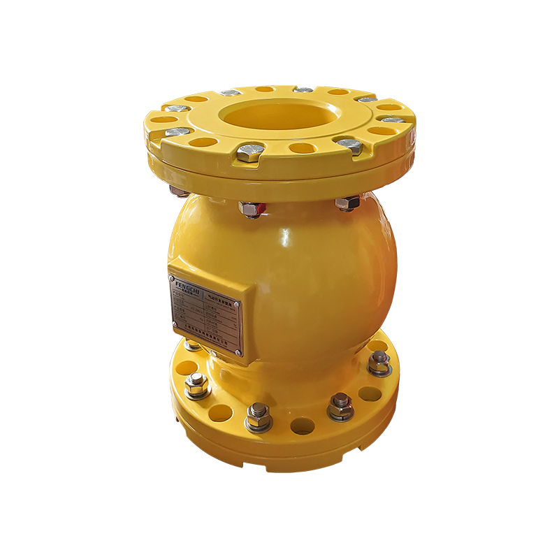
Air Operated pinch valves offer a unique and cost-effective solution for fluid control problems. The secret lies in the rubber valve sleeve - the onl...
See Details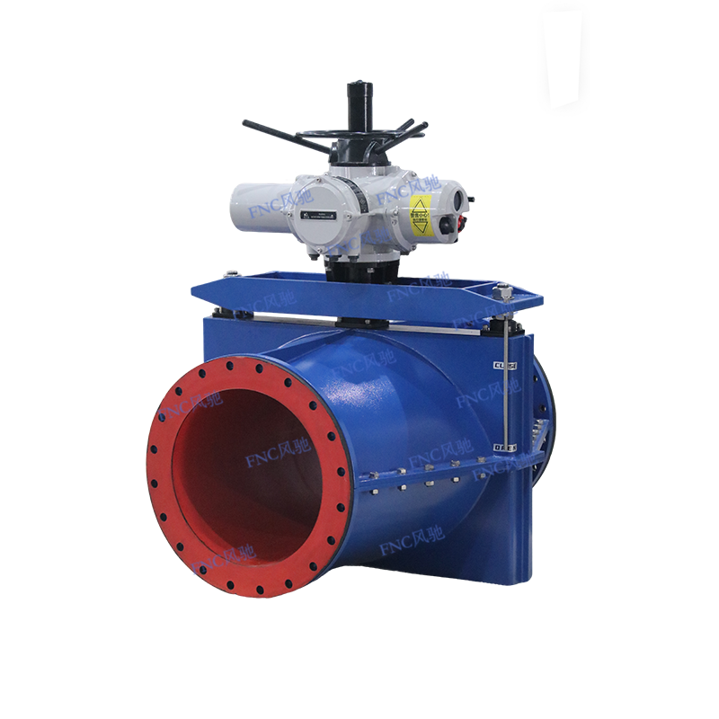
Compared to ordinary pinch valves, large-diameter pinch valves have much higher production requirements. As the “core component” of the pinch valve, t...
See Details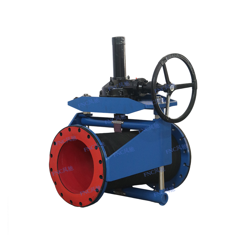
The operating principle of the FNC® enclosed pinch valve is straightforward. When in the open position, the valve provides a full-bore passage, allowi...
See Details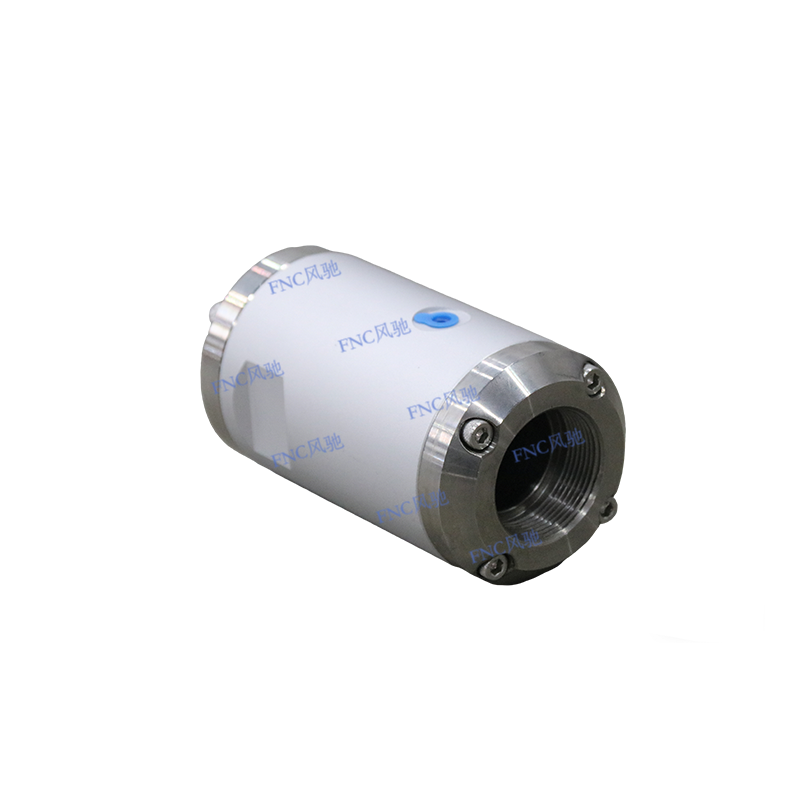
Air Operated pinch valves offer a unique and cost-effective solution for fluid control problems. The secret lies in the rubber valve sleeve - the onl...
See Details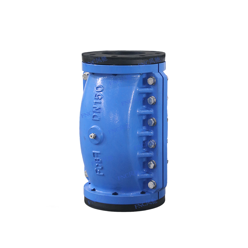
Air Operated pinch valves offer a unique and cost-effective solution for fluid control problems. The secret lies in the rubber valve sleeve - the onl...
See Details
Phone: +86-136 7173 4086

Tel: +86-563 5033 866

Email: red@pinchvalves.com.cn

Address:
